Having seen a few posts on the forum around American Racing Wheels from the US, I decided these were the business so contacted Bob Lacey at Vintage Wheels.
Bob offers a number of styles however I stuck with the more traditional 427 model that has a step in the rim. There are some smooth rims (407) model, that are slightly dearer and the extra cost helped make up my mind!
Bob proved to be a great guy to deal with and has supplied a number of AK customers previously. This is handy as it means that Bob knows all the sizes and offsets needed.
All I needed to do was decide on the wheel style and the diameter. I went for 17" rims to avoid the rubber band look of the 18"wheels and to give a little more comfort on poor UK roads.
having placed the order and paid up front, it took about a month for the wheels to arrive and I think they look amazing.
The spinners are really nice - there is a threaded boss that inserts from the back of the wheel which presents a thread at the front that the spinner screws on to. There's a grub screw that prevents the spinner coming loose.
The wheels come complete with chromed nuts and I paid extra for the 'lug covers' as our US friends call them. These are really well designed and make the wheels look like proper knock-off types.
The wheel sizes supplied by Bob were 8 x 17" front and 9.5 x 17" rears.
Tyres took a bit of research.
The AK manual suggests 215/50 17" front and 255/45 17" rears, however when visiting the AK open day, I noticed that they were fitting 225/50 fronts - which Jon confirmed.
Quite tricky finding a matched set of tyres at the differing sizes (and of a make I had heard of!) but I eventually found continental Sport Contact 5's for around £530 fitted. A quick word with the fitter made sure that due care was paid to not damaging my expensive wheels - so a shout out for F1 AutoCentre in Kidderminster for doing a great job.
All in, including import duty, VAT, tyres came to around £2600 which is about £100 less than AK can supply Image Wheels. Unfortunately, Brexit probably added £200 to my bill!.
Anyhow - here's the final effect:
Hi, this is my personal record of building an AK Cobra Replica. I'll share my progress, issues and whatever I learn in the process and hopefully it will benefit those who follow. For the record, I've built an AK Sportscars AK427 Generation 2 model with a Chevrolet 350 engine and Tremec 5 Speed transmission.
Target Car
Wednesday, 24 August 2016
Monday, 25 July 2016
Final Body Fit
I've been following the various forum threads and there seems to be a split opinion on sealing the body to the chassis. AK use a silicone sealant whereas other builders have used neoprene self adhesive strips or silentcoat sound insulation as a means of effecting a flexible joint that allows the body to be removed in future if necessary.
I spoke to AK and they said either method is OK so I opted for the neoprene strips.
I sourced 14 meters of 10mm self adhesive strip from CBS and applied it in two runs as above.
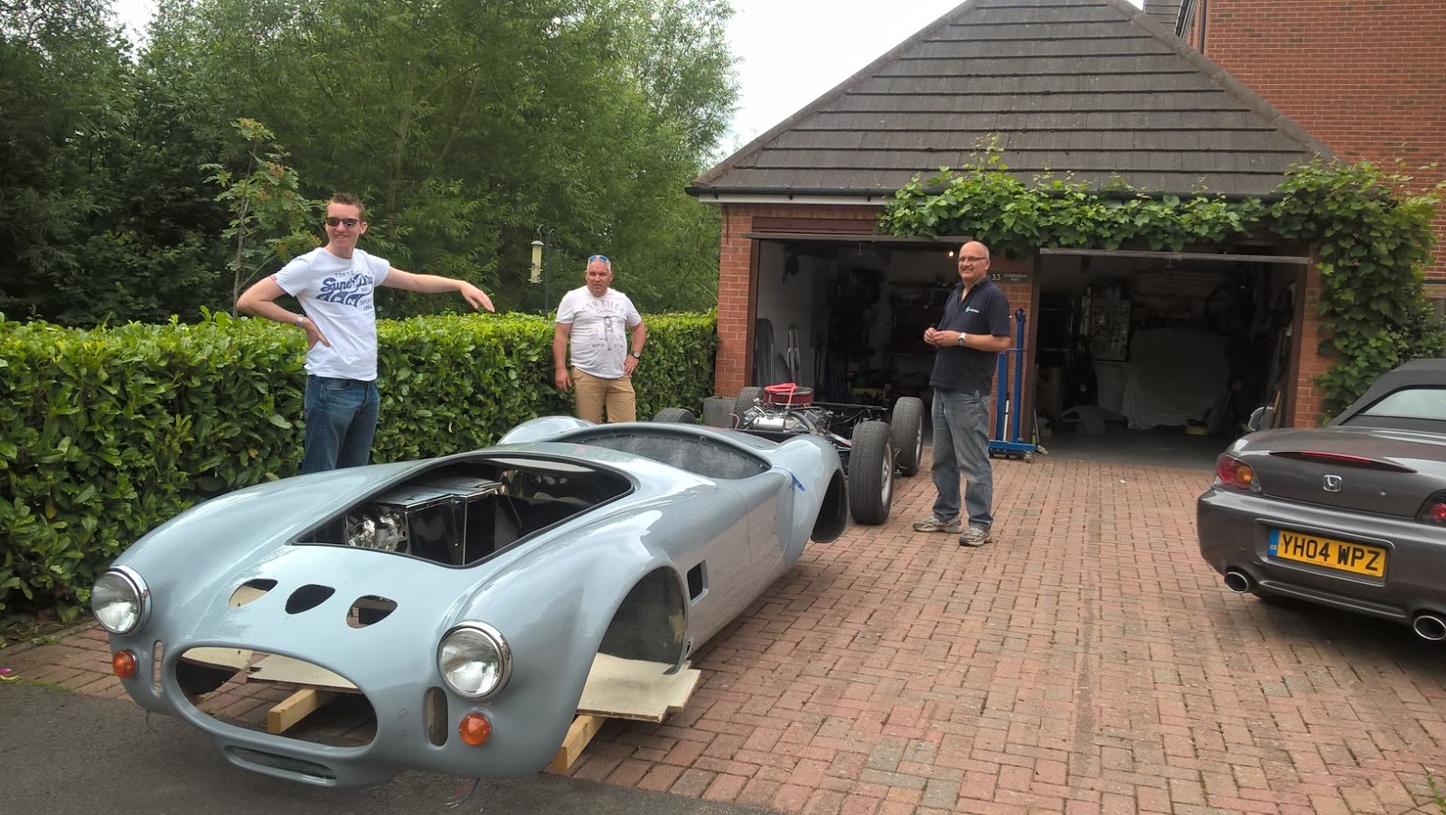
Next I arranged for some of the lads from the local car club (Midlands Ring'ers) to call in on their way back from a meet and help lift the body on for hopefully the final time.
This entertained the neighbors with an RS5, Porche Boxster and Ferrari 360 blocking the shared drive!
The lift proved uneventful as its been on and off at least 4 times now.
So that's generated some space in the garage!
In the meantime Iv'e ordered the wheels from Vintage Wheels in the US and managed to get in just before the Brexit vandals ruined the exchange rate! Hoping these will not be too long in arriving.
Monday, 11 July 2016
Handbrake
AK Handbrake performance is pretty marginal according to the various forums. There are many accounts of folks having bad experiences at IVA. I managed to get the standard setup working reasonably effectively by spending a lot of time adjusting the various pivots and the brake shoe adjusters, however it took a mighty pull on the lever to lock up the wheels and would be difficult for the wife to operate. Now in many ways that wouldn't be a bad thing however as I'm technically building this car for her I needed a solution.
A number of guys have gone down the route of fitting electric actuators, however I didn't fancy that route as I prefer to be able to hold the car on the handbrake during hill starts which is a right pain if you have to jab buttons, plus the handbrake is very much on or off.
Now as luck would have it, AK have been working on this problem and have modified the system for new builds. Fortunately they have a kit available for retro fit for £30 excl VAT.
The new system implements a pulley wheel on the end of the actuation lever which allows the cable from the actuation lever to the handbrake lever to exert double effort, thus halving the pull needed on the handbrake.
The kit comprises a modified handbrake cable, a couple of angled steel ferules and the pulley wheel and shoulder bolt.
The cable end needs to sit in a locating recess on the chassis plate. I found the easiest way to achieve this was to simply drill a small recess as above.
The net result is a much improved handbrake action with much lower effort. Well worth the cost.
A number of guys have gone down the route of fitting electric actuators, however I didn't fancy that route as I prefer to be able to hold the car on the handbrake during hill starts which is a right pain if you have to jab buttons, plus the handbrake is very much on or off.
Now as luck would have it, AK have been working on this problem and have modified the system for new builds. Fortunately they have a kit available for retro fit for £30 excl VAT.
The new system implements a pulley wheel on the end of the actuation lever which allows the cable from the actuation lever to the handbrake lever to exert double effort, thus halving the pull needed on the handbrake.
The kit comprises a modified handbrake cable, a couple of angled steel ferules and the pulley wheel and shoulder bolt.
This is the installed kit. The installation requires drilling a 12mm hole at an angle through the chassis plate to achieve a suitable angle for the cable to wrap around the pulley. The pulley fits into the hole on the actuating lever where the original cable pull located.. The threaded cable end is inserted through the two angled ferules which are then clamped in place using the two nuts. This is quite clever in that it avoids the need for any welding.
The cable end needs to sit in a locating recess on the chassis plate. I found the easiest way to achieve this was to simply drill a small recess as above.
The net result is a much improved handbrake action with much lower effort. Well worth the cost.
Monday, 16 May 2016
Getting ready for final body fitting
After the relative success of getting the engine running I thought it would be a good idea to do another test fit of the body. Bear in mind up to now I've not had the body on with the engine in situ. I also had a nagging doubt that the bonnet would close over the air cleaner.
So ripped out all the temporary wiring that took me so long to work out, removed the side pipes (which took a bit of persuasion) and enlisted the neighbors to help me and my mate, Bill Holden, to lift the body on. This turned out a bit trickier with the motor in and the technique seems to be slightly higher at the back to ease the footwells past the exhaust manifolds.
And here it is:
All bolted down so next job is to start cutting the holes for the side exhaust.
So ripped out all the temporary wiring that took me so long to work out, removed the side pipes (which took a bit of persuasion) and enlisted the neighbors to help me and my mate, Bill Holden, to lift the body on. This turned out a bit trickier with the motor in and the technique seems to be slightly higher at the back to ease the footwells past the exhaust manifolds.
And here it is:
| header tank mounted too high - adjusted the support rails to drop below the bonnet line |
| Couldn't resist fitting the headlamps. |
All bolted down so next job is to start cutting the holes for the side exhaust.
Monday, 9 May 2016
A bit of fine tuning
Well after the relative success of first engine fire I set about trying to get the engine running smoothly before making it all harder with the body on.
I bought a new timing light - this time one of the more advanced type that allows you to program in the advance required. Its so much easier than trying to work out where 15 degrees advance is with this gadget rather than guessing some point off the end of the pulley gauge. The unit I got also has a digital rev counter which comes in handy when setting the idle speed.
When I got the engine running originally, I managed to get the idle speed down to about 850 rpm as recommended, however I noticed there was fuel dripping from the venturi boosters which didn't seem right. Several hours of research later and the main reason appeared to be excess fuel pressure. Apparently these Edelbrock carb's don't like more than 6.5 psi. I'm running a Carter electric pump rated at 6psi so that shouldn't have been an issue. Just to check things out I added yet another gadget to the portfolio with a Draper Vacuum gauge which also serves as a fuel pressure tester. This measured the Carter output at 5.5psi so well within the spec for the carb.
A bit more research suggested the idle circuit could be the culprit. If its not feeding the system suitably to hold an idle, you have to set the idle screw such that the throttle plates are open more than necessary, thus using the primary boosters to supply idle fuel. When I checked out my setup, the throttle plates were definitely open more than you would expect. So, approach I took was to disassemble the carb and used an airline to blow out all jets and passages including the idle mixture threads. While I was at it, I dismantled all the choke bits as they are completely unnecessary on these engines and just get in the way.
Anyhow, put is all back together and started her up - and good news - managed to set the idle down to 850 with the throttle pretty much closed and no drips from the boosters! Happy days!
After this success, I hooked up the vacuum gauge and measured the vacuum at 15"Hg which appears to be ballpark for a medium tuned engine.I played around with the idle mixture screws as per the carb manual until engine was running smoothly with no stumbling.
I think there's more fiddling to do with this setup in future but I reckon I now have a good base.
I bought a new timing light - this time one of the more advanced type that allows you to program in the advance required. Its so much easier than trying to work out where 15 degrees advance is with this gadget rather than guessing some point off the end of the pulley gauge. The unit I got also has a digital rev counter which comes in handy when setting the idle speed.
When I got the engine running originally, I managed to get the idle speed down to about 850 rpm as recommended, however I noticed there was fuel dripping from the venturi boosters which didn't seem right. Several hours of research later and the main reason appeared to be excess fuel pressure. Apparently these Edelbrock carb's don't like more than 6.5 psi. I'm running a Carter electric pump rated at 6psi so that shouldn't have been an issue. Just to check things out I added yet another gadget to the portfolio with a Draper Vacuum gauge which also serves as a fuel pressure tester. This measured the Carter output at 5.5psi so well within the spec for the carb.
A bit more research suggested the idle circuit could be the culprit. If its not feeding the system suitably to hold an idle, you have to set the idle screw such that the throttle plates are open more than necessary, thus using the primary boosters to supply idle fuel. When I checked out my setup, the throttle plates were definitely open more than you would expect. So, approach I took was to disassemble the carb and used an airline to blow out all jets and passages including the idle mixture threads. While I was at it, I dismantled all the choke bits as they are completely unnecessary on these engines and just get in the way.
Anyhow, put is all back together and started her up - and good news - managed to set the idle down to 850 with the throttle pretty much closed and no drips from the boosters! Happy days!
After this success, I hooked up the vacuum gauge and measured the vacuum at 15"Hg which appears to be ballpark for a medium tuned engine.I played around with the idle mixture screws as per the carb manual until engine was running smoothly with no stumbling.
I think there's more fiddling to do with this setup in future but I reckon I now have a good base.
Sunday, 13 March 2016
It works!
The day had come to start the motor and I must admit to some trepidation over what might happen with all the bits I had assembled and setup.
Over the last few days I'd been pondering the startup process, read the notes supplied by Roadcraft thoroughly and surveyed the motor and ancillaries to make sure there were no issues.
First thing I noticed was that the water temperature sender and cable, No's 4, 5 and 6 spark plug boots were very close to the exhaust headers. So a quick search on line and an order followed to Thermalvelocity for some thermal boot covers.
Next step was to use the oil priming tool provided by Roadcraft to pressurise the oil system and check the oil pressure gauge and low oil pressure light. So remove the distributor, fix the tool to a variable speed drill, ignition on and rotate the oil pump clockwise. And great news - oil light went out and gauge read 50 psi.
Having taken the distributor out, the static timing needed to be reset. I already had the engine set to TDC on No1 cylinder from previously, so it was a case of rotating the distributor so that the rotor lined up with plug lead 1 on the distributor cap. This is a bit of a fiddle but from what I had read, as long as this was in line, the motor would start but would need to be advanced soon after.
Next job - connected up the timing light to sort the timing when started.
Removed the vacuum advance tube from the distributor and blocked the pipe.
Blocked the Servo input pipe on the carburetor.
Removed the Header tank pressure cap to help with any airlocks in the cooling system when the water pump started to operate.
Next part was the fuel system. I gradually filled the tank to check for any leaks on the pipework, then switched on ignition to check the fuel pump and immediately hit two problems:
1) leak on the output hose connection spayed fuel everywhere - easily fixed
2) flooding of carburetor - basically fuel was being pumped constantly into the venturis which didn't seem right! First thought was that my fuel pump was too powerful and I might need a pressure regulator. I have a Carter electric pump, and checking the spec, is rated at a max of 6.5 psi so was in tolerance for the Edelbrock carb. A bit more research pointed to the float valves not closing off the fuel supply so whipped the top off the carb, removed the floats, and removed the float valve pins, cleaned everything out as best I could then put all back together. Retested the fuel pump and problem solved - float valves were holding back the fuel supply.
A final check to make sure no loose cables, fire extinguisher close by and I gave the honor of pressing the Start button to the wife while I got ready to control the throttle.
And... it only went and started first time! - and what a noise!!. Sara was only three feet away and we had to shout to communicate. The IVA noise test might be a challenge!
I'd memorised the Roadcraft instructions and set the idle speed screw to 1500rpm, checking the timing light and adjusted the advance to approx 20 degrees as per the guide. This smoothed things out quite a bit and then spent the next 30 minutes varying the speed between 1500 and 2500 rpm which is whats recommended to run the cam in. Oil pressure all good - around 45psi, no water leaks ( Header cap was fitted soon after start.). Incredible heat off the exhausts - good job I fitted the thermal plug boots.
Water Temperature was getting up above 220 degrees F and fan cutting in and seemed to be holding it, however I was ready with the watering can to cool the radiator a bit if things got too hot.
After 30 minutes, I tried to drop the revs down to 850 to set the initial timing between 10-14 degrees but the idle was really lumpy and felt as if it was going to stall. Unfortunately my timing light packed up at this point so decided to call it a day.
Overall a great milestone achieved and plenty of reading to do about fine tuning the carb and timing for the next attempt.
Over the last few days I'd been pondering the startup process, read the notes supplied by Roadcraft thoroughly and surveyed the motor and ancillaries to make sure there were no issues.
First thing I noticed was that the water temperature sender and cable, No's 4, 5 and 6 spark plug boots were very close to the exhaust headers. So a quick search on line and an order followed to Thermalvelocity for some thermal boot covers.
Next step was to use the oil priming tool provided by Roadcraft to pressurise the oil system and check the oil pressure gauge and low oil pressure light. So remove the distributor, fix the tool to a variable speed drill, ignition on and rotate the oil pump clockwise. And great news - oil light went out and gauge read 50 psi.
Having taken the distributor out, the static timing needed to be reset. I already had the engine set to TDC on No1 cylinder from previously, so it was a case of rotating the distributor so that the rotor lined up with plug lead 1 on the distributor cap. This is a bit of a fiddle but from what I had read, as long as this was in line, the motor would start but would need to be advanced soon after.
Next job - connected up the timing light to sort the timing when started.
Removed the vacuum advance tube from the distributor and blocked the pipe.
Blocked the Servo input pipe on the carburetor.
Removed the Header tank pressure cap to help with any airlocks in the cooling system when the water pump started to operate.
Next part was the fuel system. I gradually filled the tank to check for any leaks on the pipework, then switched on ignition to check the fuel pump and immediately hit two problems:
2) flooding of carburetor - basically fuel was being pumped constantly into the venturis which didn't seem right! First thought was that my fuel pump was too powerful and I might need a pressure regulator. I have a Carter electric pump, and checking the spec, is rated at a max of 6.5 psi so was in tolerance for the Edelbrock carb. A bit more research pointed to the float valves not closing off the fuel supply so whipped the top off the carb, removed the floats, and removed the float valve pins, cleaned everything out as best I could then put all back together. Retested the fuel pump and problem solved - float valves were holding back the fuel supply.
A final check to make sure no loose cables, fire extinguisher close by and I gave the honor of pressing the Start button to the wife while I got ready to control the throttle.
And... it only went and started first time! - and what a noise!!. Sara was only three feet away and we had to shout to communicate. The IVA noise test might be a challenge!
I'd memorised the Roadcraft instructions and set the idle speed screw to 1500rpm, checking the timing light and adjusted the advance to approx 20 degrees as per the guide. This smoothed things out quite a bit and then spent the next 30 minutes varying the speed between 1500 and 2500 rpm which is whats recommended to run the cam in. Oil pressure all good - around 45psi, no water leaks ( Header cap was fitted soon after start.). Incredible heat off the exhausts - good job I fitted the thermal plug boots.
Water Temperature was getting up above 220 degrees F and fan cutting in and seemed to be holding it, however I was ready with the watering can to cool the radiator a bit if things got too hot.
After 30 minutes, I tried to drop the revs down to 850 to set the initial timing between 10-14 degrees but the idle was really lumpy and felt as if it was going to stall. Unfortunately my timing light packed up at this point so decided to call it a day.
Overall a great milestone achieved and plenty of reading to do about fine tuning the carb and timing for the next attempt.
Monday, 7 March 2016
Nearly Ready to Start it....
Well progress has slowed a little with the bad weather and cold temperatures in the garage, plus the missus taking issue with me having any heating on!
Anyhow, I have managed to progress to the stage where I'm nearly ready for the first start.
The main tasks have been fitting the header tank and hoses then making up temporary wiring to ensure all the basic engine functions are covered.
Header Tank
As per my last post, I decided to go off-piste with this item and not use the expensive (but beautiful) AK Stainless item. I might decide to change to this later on but at this stage I need to keep costs down.
Lots of research and I decided on an alloy item from OBP. Their standard unit had the outlets in the wrong place but they do a bespoke service and modified one to suit for around £80 all in.
I made a couple of mounting brackets out of aluminium square section I had lying around and used a modular adapter from CBS for the junction between the top hose and the header pipe.
This fitting has the temperature sensor for the cooling fan and I drilled and tapped the side of the fitting to accept a CBS hose outlet. So all in all its cost around £120 for all the parts, over £300 for the 'proper' one.

After this the next job was filling with antifreeze. Lots of different opinions on the web over what sort of antifreeze to use. When I was a lad it was Bluecol or nothing! So now I know all about OAT, Silicates, Pink, Blue and goodness knows what else - oh , don't forget water-less coolant! In the end I settled for Halfords Blue ready mixed which looks a good compromise for mixed alloy/iron engines.
What you forget is how big these engines are and how much coolant they take. Not far off 15 litres is the answer. I had one or two minor leaks from the hoses and from the temperature sender on the head that I hadn't tightened properly but all sorted now.
I raised the front of the car as high as I dared using the engine crane during the fill up to help getting the air out of the system. - Hope it worked!
Electrics
I decided to lash up my own temporary starter loom just for the engine test.
I made up a drawing with the basic plot, identifying all the connections needed and cable capacities. This enabled me to tick off each leg as I went.
I made a small mounting panel to house the various switches and gauges during the test run and a small stand for mounting the electric fuel pump. Some folks fit these to the inner chassis rail in front of the diff, however the carter unit I have is the wrong shape to easily fit there. Mine is going on the bulkhead wall around the transmission tunnel, nearside as have a few other builders.
I realised I would need:
List of connections:
300 AMP Red Battery cable to from Battery +ve to Starter Motor Main terminal.
300 AMP Black Battery cable from battery -ve to Chassis ( via a battery isolator switch)
100 AMP Red cable from Alternator Output to Starter Motor Main terminal.
8 Amp cable with 5Amp fuse from Alternator Output to Alternator Input.
Rev Counter output cable to rev Counter ( Set rev counter to V8 pulse pattern)
Keyed Ignition Switch:
27 Amp cable from Battery +ve to Battery input terminal on key switch
Created a switched live feed (27A) from the auxiliary connection on Keyed Ignition Switch.
Use this feed for any services that operate with Ignition ON.
8 Amp cable to Fuel Pump +ve
8 Amp cable from Fuel Pump -ve to chassis.
8 Amp cable to Distributor input.
30 Amp relay ( for cooling fan) 17 AMP cable from Battery +ve to load input on relay.
17 Amp cable from Relay load output to Fan input.
17 Amp cable from Fan output to chassis.
8 Amp cable from switched live to fan thermostat input.
8 Amp cable from fan thermostat output to relay switch input.
8 amp cable from relay switch output to chassis.
8 Amp cable from Alternator Charge light terminal to a red Indicator lamp.
8 Amp cable from Indicator lamp to switched live.
Starter Button
8 Amp cable from switched live to Starter Button input.
8 Amp cable from Starter Button output to 50 AMP Starter Relay switched input.
8 Amp cable from 50 Amp Starter Relay switched output to chassis.
27 Amp cable from Battery +ve to 50 Amp relav load input.
27 Amp cable from 50 Amp relay load output to Starter Solenoid.
Instruments
Rev Counter - live feed connected to switched live.
Rev Counter - earth wire to chassis
Water Temperature gauge - link cable to temperature sender.
Water Temperature gauge - live feed to switched live, earth wire to chassis.
Oil pressure - link cable to pressure sender
Oil pressure - live feed to switched live, earth wire to chassis.
Oil pressure warning light - 8 Amp cable from pressure switch to warning light.
8 Amp cable from warning light to switched live.
So after all that Its off to get some fuel!
Anyhow, I have managed to progress to the stage where I'm nearly ready for the first start.
The main tasks have been fitting the header tank and hoses then making up temporary wiring to ensure all the basic engine functions are covered.
Header Tank
As per my last post, I decided to go off-piste with this item and not use the expensive (but beautiful) AK Stainless item. I might decide to change to this later on but at this stage I need to keep costs down.
Lots of research and I decided on an alloy item from OBP. Their standard unit had the outlets in the wrong place but they do a bespoke service and modified one to suit for around £80 all in.
I made a couple of mounting brackets out of aluminium square section I had lying around and used a modular adapter from CBS for the junction between the top hose and the header pipe.
This fitting has the temperature sensor for the cooling fan and I drilled and tapped the side of the fitting to accept a CBS hose outlet. So all in all its cost around £120 for all the parts, over £300 for the 'proper' one.
After this the next job was filling with antifreeze. Lots of different opinions on the web over what sort of antifreeze to use. When I was a lad it was Bluecol or nothing! So now I know all about OAT, Silicates, Pink, Blue and goodness knows what else - oh , don't forget water-less coolant! In the end I settled for Halfords Blue ready mixed which looks a good compromise for mixed alloy/iron engines.
What you forget is how big these engines are and how much coolant they take. Not far off 15 litres is the answer. I had one or two minor leaks from the hoses and from the temperature sender on the head that I hadn't tightened properly but all sorted now.
I raised the front of the car as high as I dared using the engine crane during the fill up to help getting the air out of the system. - Hope it worked!
Electrics
I decided to lash up my own temporary starter loom just for the engine test.
I made up a drawing with the basic plot, identifying all the connections needed and cable capacities. This enabled me to tick off each leg as I went.
I made a small mounting panel to house the various switches and gauges during the test run and a small stand for mounting the electric fuel pump. Some folks fit these to the inner chassis rail in front of the diff, however the carter unit I have is the wrong shape to easily fit there. Mine is going on the bulkhead wall around the transmission tunnel, nearside as have a few other builders.
I realised I would need:
- Ignition Key Switch
- Starter Button
- Electric Fan, temperature switch and relay.
- Fuel Pump
- Starter relay
- Oil pressure warning light.
- Ignition warning light
- Battery - 072
- Battery cables
- Power to Distributor and fuel pump.
- Power feed from Alternator to battery
- Rev Counter
- Oil Pressure gauge
- Water Temperature gauge
List of connections:
300 AMP Red Battery cable to from Battery +ve to Starter Motor Main terminal.
300 AMP Black Battery cable from battery -ve to Chassis ( via a battery isolator switch)
100 AMP Red cable from Alternator Output to Starter Motor Main terminal.
8 Amp cable with 5Amp fuse from Alternator Output to Alternator Input.
Rev Counter output cable to rev Counter ( Set rev counter to V8 pulse pattern)
Keyed Ignition Switch:
27 Amp cable from Battery +ve to Battery input terminal on key switch
Created a switched live feed (27A) from the auxiliary connection on Keyed Ignition Switch.
Use this feed for any services that operate with Ignition ON.
8 Amp cable to Fuel Pump +ve
8 Amp cable from Fuel Pump -ve to chassis.
8 Amp cable to Distributor input.
30 Amp relay ( for cooling fan) 17 AMP cable from Battery +ve to load input on relay.
17 Amp cable from Relay load output to Fan input.
17 Amp cable from Fan output to chassis.
8 Amp cable from switched live to fan thermostat input.
8 Amp cable from fan thermostat output to relay switch input.
8 amp cable from relay switch output to chassis.
8 Amp cable from Alternator Charge light terminal to a red Indicator lamp.
8 Amp cable from Indicator lamp to switched live.
Starter Button
8 Amp cable from switched live to Starter Button input.
8 Amp cable from Starter Button output to 50 AMP Starter Relay switched input.
8 Amp cable from 50 Amp Starter Relay switched output to chassis.
27 Amp cable from Battery +ve to 50 Amp relav load input.
27 Amp cable from 50 Amp relay load output to Starter Solenoid.
Instruments
Rev Counter - live feed connected to switched live.
Rev Counter - earth wire to chassis
Water Temperature gauge - link cable to temperature sender.
Water Temperature gauge - live feed to switched live, earth wire to chassis.
Oil pressure - link cable to pressure sender
Oil pressure - live feed to switched live, earth wire to chassis.
Oil pressure warning light - 8 Amp cable from pressure switch to warning light.
8 Amp cable from warning light to switched live.
| A bit messy - taken prior to fitting cable ties - but it all works! |
| Temporary starter panel |
So after all that Its off to get some fuel!
Subscribe to:
Posts (Atom)