Target Car

Target Car

Friday 22 December 2017

Rebuild after paint

Now for the part I've been looking forward to - refitting all the shiny bits for hopefully the last time!

I've started at the front with the overriders and lights and fitted the nose cone vents. I know these are individual taste but my missus thinks they are great!

Fitting the vents is quite straightforward using body filler and holding them in place until the filler goes off. Then apply more filler underneath to ensure they stay put.

One thing that other builders have said - and they are right - is the fear factor of working on the car after paint. No more leaving tools on the wings!


Saturday 11 November 2017

Dashboard


Fitting the dials, switches and lamps took a surprising amount of time but the good news was I could do this in the dining room rather than in a cold garage!
Some of the holes in the fibreglass came up too small to tuck the leather through with the switches but this was fixed by carefully opening up the holes with the Dremmel. Its not too scary to do as the padding separates the leather from the fibreglass.

Here's my first attempt at wiring everything up. Not as neat as some I've seen and even though its going to be hidden its on my list for rework.

Paint

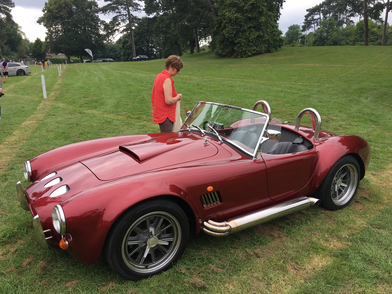
It’s back, and a great job done by Option 1 Sportscars.
We are very pleased with choice of colour, Aston Martin Diavolo Red which has some depth to it and works well with the curves. This is a change from our original thinking of a candy colour but we were persuaded to avoid the three stage complex colours as you could be looking at a total respray if a repair needed. Based on the result this looks like good advice.


Monday 9 October 2017

Door alignment

I'd previously fitted the door catches as per the manual which requires the doors to be aligned with the body then fitting the door catches to the door with spacers to simulate the thickness of the door card. The recommendation is the thickness of the untrimmed door card plus 5mm. This assumes you are fixing the trimmed door card behind the catch and not cutting the trim around the catch.

To work out where to fit the striker and striker plate I clipped the striker into the door catch, then with the door aligned, marked he striker location and striker plate. Its then a case of cutting some wooden blocks to support the striker plate - then using lots of P38 filler to hold it all in place. Then leave it all to set for a good 24 hours.
Striker, striker plate and tube spacer. Note the striker plate is
proud of the door flange.
I also used some 1/2" steel tube as a spacer between the striker head and the striker plate to improve the rigidity.

So I followed this to the letter and ended up with a great door fit and nice action between the catch and striker.

Striker plate filed down flush.


Next thing was to fit the internal door frame finisher and this is where I found a difference on each side of the car. On the drivers side - no problems. On the passenger side, the striker plate ended up proud of the body lip - which meant I had to file it down to get it anywhere near flush. I used a power file for this  - a lot safer than a grinder.   What this meant was where I could fit the full fibreglass finisher on the drivers side - I had to trim the passenger side so that it finished below the striker plate - else when carpeted it would be sticking out too far.
Passenger side internal finisher - trimmed at top


Next up was to fit the fully trimmed door cards - and this is where the problems started. Basically the thickness of the door card combined with the AK supplied seal meant that the door would not shut correctly and bowed out at the bottom.

The problem was that I'd made the door cards too deep (top to bottom) so the only route forward was to trim the bottom of the cards so that the door seal presses more on the door rather than the card. Now this is easier than it sounds once the card has been trimmed. The leather covering  - which is glued down - has to be carefully peeled back which then allows the bottom edge of the card to be sanded down. Then followed multiple test fits, more sanding , more test fits until I reached a point where the door would fit flush. I used the  power file to ease the operation and beveled the card edge  to try and get some sort of seal between the card and the seal. I then  used leather adhesive to re-fix the leather trim. Lots of hours went into this but its so important to get this right.
In hindsight its better that I had made the cards too big than the other way round!.


Showing the passenger side latch and cut-down inner finisher.

Finished door card

Door seal fitting


The next issue I had concerned the drivers side door latch. The lever is simply an interference fit onto the short shaft that acts as the fulcrum. As the door lock was a bit stiff - and the lever will tend to twist when force is applied -  I managed to dislodge the lever from the fulcrum. I'm thinking this needs to be pretty robust in real life and was toying with returning it to S&J Motors for a replacement.  In the end and to avoid delays I fitted a flat head bolt a couple of thin washers and a nylock to hold it all in place. This meant drilling a clearance hole into the door card and the door skin itself (you don't need these with the standard lock as the rear face is flat.).
In my opinion the result is a lot more robust and I plan to modify the passenger side to match.


Standard latch assembly with pressed-on lever

Modified lever assembly with location bolt.


Off to the body shop

This post is out of sync with the work I've been doing to get the car ready for painting but today's the day its away to the body shop for final preparation and paint.

We've chosen to go with Option1 Sportscars in Bromsgrove. This follows a fair bit of research and weighing up the pro's and cons of the various companies.

In the end we got down to a choice between Option1 and AK's next door neighbours who, granted, do a great job on AK's demo and customer cars.

Andy Menzies picked Option1 for his car and was kind enough to show us round his stunning motor. This was enough to convince me that these guys were a good choice and know what they are doing with composite bodywork. The clincher was they are only 30 minutes away. Frank, the owner, came round one Sunday morning to look over the car and confirm the telephone quote previously given and explained the process they go through to prepare and paint.

So off it goes and I can look to tidy the garage ready for the return!
All undressed ready for the paint shop


Friday 28 July 2017

Interior

Interior has arrived and a great job done by AK's in-house trimmer Dougie.
The colour is Anthracite grey, perforated leather with red stitching.
The tunnel cover is also leather covered which we think will be more practical than carpet.


Friday 2 June 2017

Colours and interior

As I'm technically building this car for "she who must be obeyed" - the recent trip to the kit car show and the AK stand in particular looks like its going to increase the budget somewhat.

She's always wanted it Red and I thought I'd get away with a standard Jaguar off-the shelf colour.
Unfortunately she's decided on the new AK demo car colour which is a dark cherry - candy. Basically its a candy apple red painted on a black undercoat.

Now she says this is what she always wanted and that Wendy and Jon have nicked her idea! However - I've had a quote and its a lot more than I was planning.

AK demo car - "Rufus"

We won't be having the stripes!

For the interior I was going to go with a standard interior with the carpeted rear bulkhead. I personally don't see the point of doing that bit in leather. However - we've placed an order for a full leather interior including the rear bulkhead and thrown in a leather covered tunnel for good measure. The colour scheme is anthracite with perforated leather.

 - I wonder who wears the trousers in our house?

Brake Light Switch

There are a couple of options for the brake light switch:

  • Pressure switch added to brake circuit
  • Micro switch connected to brake lever


I've chosen the later route - I don't think there's a right or wrong way however.

So I've used a small switch from CBS and constructed a bracket attached to the pedal box.

The bracket prevents the switch from rotating and is strong enough to resist knocks but is well out of reach of your foot on the brake pedal.

When the assembly is fitted to the car - I found that the lever did not fully return to make contact with the switch  - so the brake lights were permanently on. I adjusted this by adding a clip to the brake lever to make up the gap.
With this arrangement, the lightest touch on the pedal gets the lights on.


Micro Switch 


Friday 26 May 2017

Throttle Linkage

Getting closer to running the car with the body on so time to address the throttle connection. Different builders have approached this in different styles but the key messages I picked up from the forum were:


  • Need strong enough return springs to fully close the throttle and raise the pedal.
  • Need to avoid any side load on the throttle spindle - to avoid wear on the bearing.


Some guys have bought linkage kits between £30 - 50 whilst others have manufactured one. From what I can see, the guys who have bought kits have had to modify them for height etc so I thought I might as well go down the fully custom route.

I built a prototype out of 1.5mm aluminium along with some scrap aluminium angles to prove it out then built the final version from 5mm aluminium plate. A 250mm x 125mm plate from the local stockist was £3.
I used a 6mm cable adjuster and two return springs from CBS.
I'm using a universal cable from halfords - this was only about £3 and works really well, partially as I found a route that avoids any severe bends.
Final upgrades are to add a rubber cable bellow ( on order from CBS)  and to improve the cable connection to the throttle lever.


This design keeps the forces in line and avoids a high load on the spindle bearing

In situ - cable bellow not fitted in this picture
Looks quite neat - hidden by the air cleaner

Thursday 11 May 2017

Wiring part 2


A while since my last update, so if anyone thought I'd given up that's far from the case.


Reversing Light/Fog Light

I'm not planning on using a rear chrome bumper so needed the lamps to be fitted to the body. I quite like the inserted look that AK recommend, however if I'd have realised how much work is involved I'd have gone another route!
Cutting the holes out is not too bad with the Dremmel,  however I found that I had to remove a small section of the boot floor in the process, else the lamps would be too low down on the valance.
I used S&J's lamps that needed modifying slightly to re-route the cable exit, and made up some blocks to fix the back of the lamp case to the chassis rail. Sounds easy but was a right pain. Once fitted, I fibreglassed the boot floor above the lamps to fill in the gap. The final issue is getting a neat finish around the lamp so several filling/sanding operations were needed to complete.


View from above showing the bit of the boot floor  removed. 


Finished Item


Battery Fit


I looked at a few battery trays but realised that the height of the battery meant that it really needed to sit on the boot floor else the -ve post was too close to the body to easily fit/remove the -ve terminal.

So I used a simple angle bracket as a backstop and a tie-down battery bracket from Halfords. The hooks just go through holes in the boot floor which I re-enforced with penny washers. In the final fit  - I'll be sealing the holes with silicone to stop water ingress.


Dashboard wiring.

I decided that it would be a good idea to wire up the dash and column stalks with the dash untrimmed so that I could make sure all was well and working before sending the dash away to be covered. I know this means a strip down and redo job but just felt that I could iron out any issues before I have a finished part on my hands.

So for my dashboard design I played around with a some cut out templates to arrive at a suitable layout. I've not opted for a clock hence the four ancillary gauges

  • Volts,
  • Oil Pressure,
  •  Fuel
  • Water Temp.

I've added a power socket and USB ports in the back of the glove box.

The switches are Savage type from CBS.
I've opted for

  • Large Start Button
  • Cooling Fan Override Switch ( in case fan doesn't cut in)
  • Screen fan
  • Hazard Warning
  • Brake Test Switch
  • Rear Fog Light


I haven't used the usual two lighting buttons as to me that looks a little clumsy so I've used a single rotary switch mounted above the ignition key and in the allowed projection area for IVA.


Mock up
Acceptance test from the boss
A really dusty job
Pretty lights!


Column Stalks.

I have a BMW E36 Indicator assembly - which as you might expect does not adhere to either the E30 or E34 wiring instructions in the manual.
This is the E34 wiring guide with notes around the differences with the E36..


Lights
BMW Switch                                      AK Wiring Loom
Green/Yellow (Pin 10)                         Red/White                          Note – there are two Green/Yellow                                                                                                                   cables into Pin 10 on the E36
Yellow                                                   Blue/Red
White                                                    Blue/White


Indicators
BMW Switch                                      AK Wiring Loom
Green/Yellow(Pin 5)                       Lt Brown/Lt Green              Note – no Green/Yellow in Pin 5 –                                                                                                                     looks like Grey/Red
Blue                                                       Green/White

Grey                                                      Green/Red


Advice from AK was to connect one of the Green/Yellow cables from Pin 10 to Lt Brown Lt Green connection.
What I discovered is that one of the green/yellow wires is for the lights and the other for the indicators. I got them the wrong way round at first and had the main beam flashing nicely in time with the indicators. My advice is to make these connections with bullet or spade connectors so you can easily swap over if you get it the wrong way round.
The Wiper stalk conforms exactly to the AK wiring manual. You have to make up the connector from the kit supplied but in my case the wipers and washers all worked first time.


Handbrake/Low Brake Fluid Level


I'm using a Savage Switch for by Brake Level test light so this illuminates when either the fluid is low or the handbrake is on. This is enough for IVA, however I thought it would be neat to also allow the lamp to be tested by pressing the Savage switch.

The wiring manual doesn't give much help when trying to connect up the brake level lamp as essentially you have a Blue/Red wire that links the Handbrake, Low Fluid switch and the lamp.The Red/Blue link wire is not powered at all, so I worked out that if I connected the lamp to +12v then used the Red/Blue wire as a route to earth via the switches - all would be well. With this arrangement, any of the three switches will light the lamp - i.e. a parallel set up.

All works nicely.